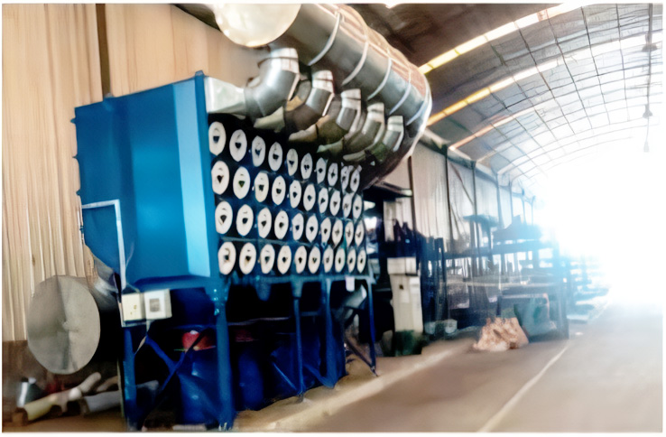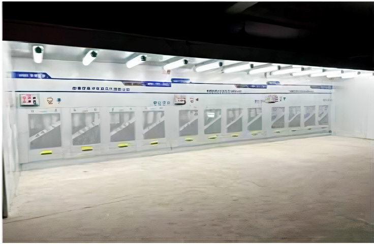

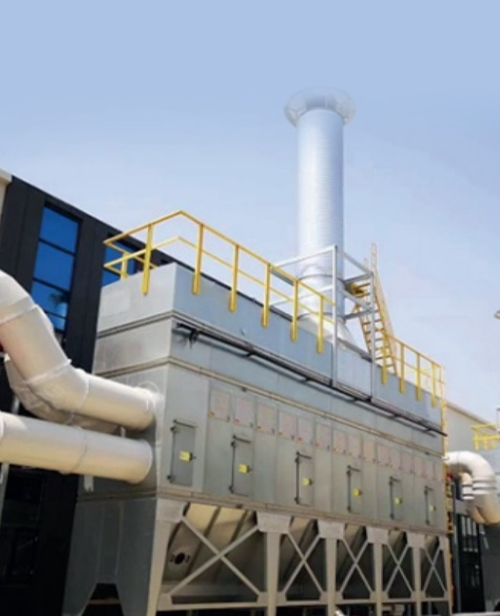
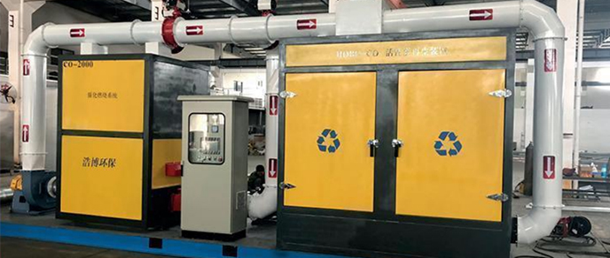
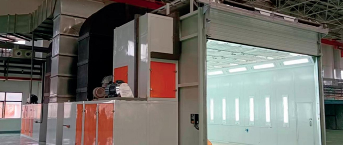
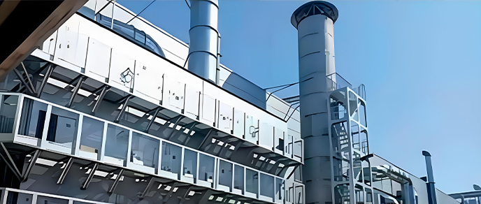
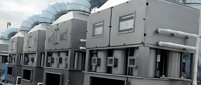
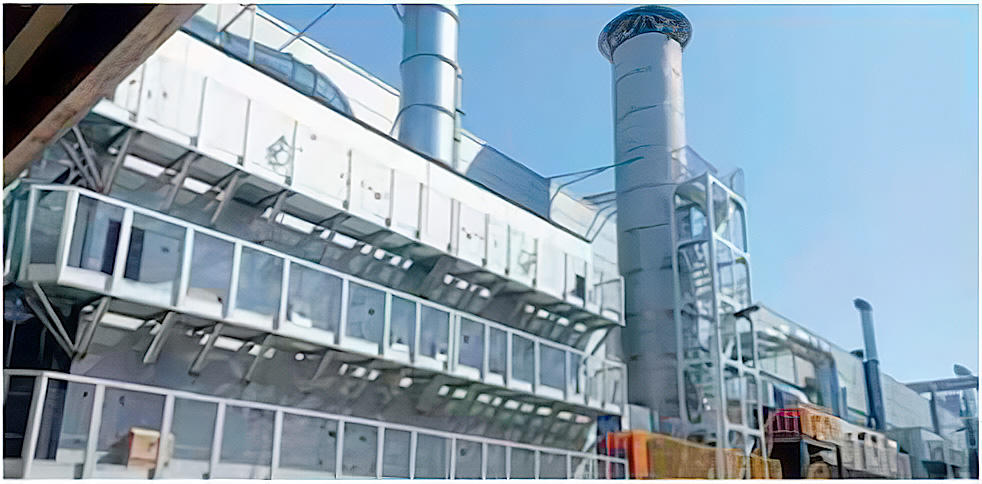
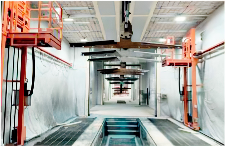
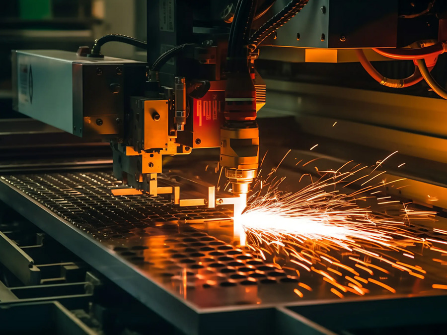
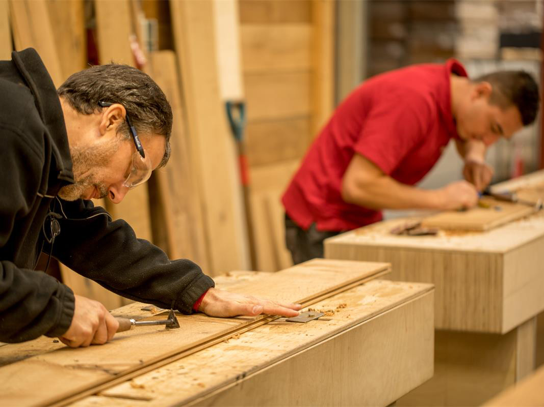



Dust removal pipeline layout
2026.01.14

Optimized Dust Collection Pipeline Layout for Wood Processing Facility
1. Introduction
This case study examines the redesign and implementation of an industrial dust collection pipeline network at a high-volume wood processing plant in Sweden. The project addressed critical challenges in airflow efficiency, fire safety, and maintenance accessibility while complying with stringent EU ATEX and ISO 21940-2 vibration standards. The new system serves 48 woodworking machines across a 12,000m² facility with a total airflow capacity of 85,000 CFM.
Key Objectives
- Achieve ≤15 m/s transport velocity for optimal particulate conveyance
- Reduce pressure drop by 35% compared to legacy system
- Implement explosion-proof measures for combustible wood dust (Kst >200 bar·m/s)
2. Pipeline Design & Engineering Solutions
2.1 System Configuration Overview
| Parameter | Specification | Innovation Feature |
|---|---|---|
| Main Duct | Spiral-wound galvanized steel (Ø800-1200mm) | Internal polyurethane coating reduces friction loss |
| Branch Lines | Modular aluminum (Ø300-500mm) | Quick-disconnect clamps for machine reconfiguration |
| Support System | Vibration-isolated hangers (50mm neoprene pads) | Finite element analysis-optimized spacing |
| Monitoring | IoT-enabled pressure sensors (Class I Div 2) | Real-time CFD model calibration |
2.2 Critical Design Innovations
- Aerodynamic Optimization:
- Venturi-shaped branch entries reduce turbulence by 62%
- 7° gradual elbows minimize particle deposition
- Safety Systems:
- Rotary air locks isolate explosion zones per NFPA 68
- Spark detection triggers 0.1s deluge system response
- Maintenance Enhancements:
- Retractable cleaning hatches every 15 meters
- Magnetic inspection ports for borescope access
3. Installation & Performance Validation
3.1 Phased Implementation
- Phase 1 (Weeks 1-4): Laser scanning of existing facility for BIM modeling
- Phase 2 (Weeks 5-10): Nightshift installation to maintain production (57 welds X-ray inspected)
- Phase 3 (Week 11): Airflow balancing with computerized damper adjustment
3.2 Performance Metrics
| Metric | Original System | New Design | Improvement |
|---|---|---|---|
| Pressure Drop | 28″ w.g. | 16″ w.g. | 43% ↓ |
| Energy Use | 185 kW | 112 kW | 39% ↓ |
| Maintenance Hours | 140/month | 35/month | 75% ↓ |
3.3 Operational Benefits
- Fire Safety Upgrade: Reduced explosion risk from 1 incident/3 years to zero in 18 months
- Noise Reduction: 92 dBA to 81 dBA at operator stations
- Flexibility: 2-hour machine relocation vs. 2-day previously
4. Smart Monitoring & Future Adaptations
4.1 IIoT Integration
- Digital Twin: Updates every 15 minutes with actual pressure/flow data
- Predictive Cleaning: AI analyzes pressure differentials to schedule blasts
- Material Tracking: RFID tags on duct sections for lifecycle management
4.2 Cross-Industry Applications
- Metalworking: Stainless steel variant for grinding dust
- Pharmaceutical: Hygienic design with CIP spray balls
- Food Processing: Anti-static version for flour dust
5. Conclusion
This pipeline optimization project demonstrates how advanced fluid dynamics modeling and modular design can transform industrial dust collection systems. The solution achieved 98.2% particulate capture efficiency while reducing total cost of ownership by 28% over 5 years.